Database driven state diagram

Jaromír Junek     WEB

Intro

This article describes a new way of dealing with relatively complex status diagram driven control systems which I developed for my own use. It may inspire someone else to use it for his/her own projects.

Many of the real-time processess can be described by means of a Status diagram which is perfectly fine for systems without complicated timing dependencies.

When there are many processes running independently, each of them can be described by its own state diagram.

In cases where processes have their own timing and needs to be mutually synchronized, status diagrams become a bit impractical for describing mutual relations between processes and programming of the many intertwined processes can easily become a nightmare.

Sometimes, it is necessary to set some parameters on the target system. If there are many of them and they are part of the status machine it is useful to represent them in the state diagram for easy modifing of their values.

There are following aspects of the problem

  1. how to graphically represent the state machines and their mutual dependencies
  2. how to easily convert the graphical representation to a code
  3. how to easily browse the code
  4. how to verify that the real target system behaves as expected

1. Graphical representation
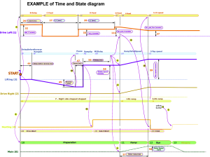
For state machines with a lot of branching classical state diagram is probably the best tool. On the other hand, for processes mutually dependent based mainly on the timing, the solution is to use time-based reprenentation of each process including its states and process synchronization

2-3. Converting graphical representation to a code and code browsing
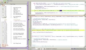
Standard implementation of the state machine is one big switch statement where each node (case) represents one state and the action are taken based on testing various conditions. The conditions and transition actions are usually placed in the case statement. In case of status machine with many states and many conditions, it is usally difficult to navigate, especially after some time of writing of the code.

4. Tracing the behaviour of the target real-time system
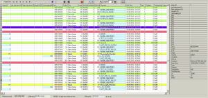
Very often it is necessary to verify that the target system software executes correctly and that the timing is as expected. For this purpose it is a good idea to log the transition changes in the database and evaluate what was happening on the target system and when. The log is bound to the source code so that it is easy to trace the state transition in the log and watch the appropriate source code at the same time.

Each column in the log table represents one state diagram. Colors diferentiate events: state changes, signals, debug informations. As the target system keeps track of the real time which is used for event logging, it is possible to measure time between events in the log.

The log is automatically stored in the database. If needed it wouldn't be a big problem to write a program simulating target system behavior based on the log or compare behaviour of the target system when it is working correctly and when it is misbehaving.
Solution

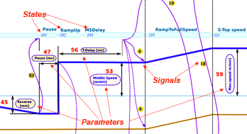
To solve this problem I designed a new technique - database driven state machine. The trick lies in describing the state diagrams, their states and transitions between states in the database. For documentation purpose the processes are represented in the processes graph.

Program automatically generates code representing the states machines from the data stored in the database. The output is a source code, consisting of two main parts:

  • Each state machine has its own switch where conditions are based on the database data
  • Transitions which are generated as an empty templates where a programmer puts the transition action code

Keep the track of the code

For easy navigation in the code, tree structure of the state machines, states, conditions and transition actions is automatically generated allowing to jump right into code of the required transition.

Terminology

A years ago when I was working on a relatively complicated control process implementation I used to draw the states diagram in hand on a big sheet of paper. The ovals representing states looked more or less like a potatoes in my drawing so I started to call them "brambora" which is czech word for potato. So the state diagram get also its name - "bramborak" which is a meal made from potatoes.

To my surprise when I did some job for this company twenty years later I found that these terms are still in use and not only in this company but also in the cooperating german company.

So if you observe in the following description words brambora o bramborak now you now what it means.

Implementation

Conditions

Basically, there are three types of condition upon which the state machine changes its internal state:

  • Signal from the same or from another state machine
  • Timeout
  • General, user defined condition

Database structures

State machines data are stored in several tables. The most important are

  • State machines - the list of state machines and their description
  • States - the list of states of each state machine
  • Transitions - the list of transitions between states
  • Signals - the list of signals for synchronization between tasks
  • Event log - history of the real-time transition changes and other events like signal activating. Each event is marked by a timestamp

Target code structure

Based on the database data, the source code implementing the state machines is automatically generated including the tree representation of the code. In my implementation I needed to generate C-code for controlling the target system so that both .c-file and .h header file is automatically generated and it is open in a smart text editor.

If needed the program could be modified to generated source code other then C-language.

The tree contains the list of state machines on the top level with transitions of the state machines as branches and conditions as leaves. By double-clicking on a transition, the condition function and transition function of the particular transition is located and marked in the smart text editor. A programmer task is to write a code implementing an action for the transition and possibly the condition function if the condition in not a timeout neither a signal.

Parameters definition

Often some parameters are part of the state diagram and it is necessary to modify them in the running process.

Small number of parameters can be easily managed by a parameter table and everybody is able to orient himself in this table. On the other hand - if number of parameters is more than let's say twenty or thirty it becomes difficult to remember meaning of each of them and in case I was working on with about 200 parameters it would be practically imposible to change these parameters by looking them up in a table.

The problem solution called for some kind of graphicaly represented parameters bound to the state diagram. As a result, I put all the parameters data to the database table and its graphical representation to the graph of state machine diagrams. This way, user can click inside the graph to the parameter name inside a frame and a dialog window appears where it is possible to see / modify the parameter value. For keeping track of the parameters changes, all the changes are stored in the database too so it is possible to look at the previous values of a parameter and date/time of the change.

Some of the parameters can be a value of a timeout in the state diagram. In my program I automatically generate a C-source code with all variables (=parameters) definition and a code for transferring the variables from PC to the target system. As these parameters can be used in the database table describing the state machine transitions, the behaviour of the state machines can be controlled by changing the parameters on PC in the real-time.

Formulas in parameters

Sometimes it is necessary to set a parameter in units different from the units required in the target system. If this is the case, a formula can be defined inside the parameters table. This formula is used before the parameter is sent to the target system for recalculation ot he value. The formula can use its own (user specified) value as well as a value of another parameter in the parameter table.

For example, the formula []*sin([12])+3*[28] calculate the result value as: (value of self) times sin(value of parameter#12) plus 3 times (value of parameter#28 ).

Resume

After a couple of years uf using this metodology I am able to summarize the advantages of this solution.

At first look it looks like a lot of burden to prepare all the graphs and tables, but for non-trivial systems it shurely pays off both in the time of program creation but even more in the time of keeping system up to date during its life-span which sometimes can count in years since its release.

The most obvious advantage is a good documentation of the program so that an author is able to easily understand and/or modify the program even years after the first release. This goes well even more if someone else is taking over the project and has to get involved in a short time.

The tree representation of the state machines is a fast way of navigation in the source code and prevents writing code in the "wrong" place. Programmer has an instant access both to the condition testing and to the transition actions which allows quick modification of a program.


Last edited: 20.11.2016